High-Pressure Solutions

Balanced Mechanical Seals

Balanced Mechanical Seal ⚡ Hydraulic Balance Ratio

Technical Data

  • Balance Ratio (β): 0.65 – 0.85
  • Pressure Limit: Up to 50 bar
  • Temp. Range: -50°C to 300°C
  • Sliding Speed: Up to 25 m/s
  • Standard Materials: SiC / TC / Carbon
  • Elastomers: Viton / FFKM / PTFE

Hydraulically Balanced Performance

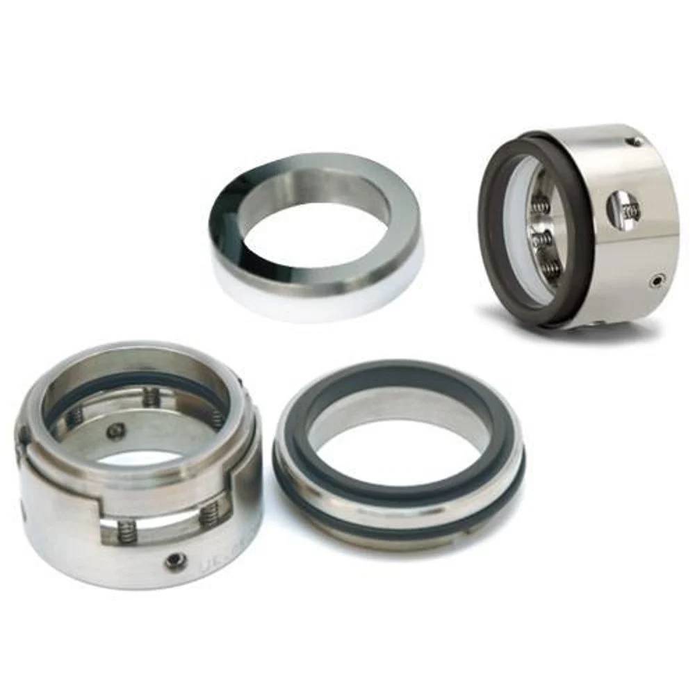
Balanced mechanical seals represent the ideal solution for handling high-pressure liquids, volatile hydrocarbons, and flashing fluids. The fundamental difference between balanced and unbalanced mechanical seals lies in the hydraulic design: a balanced seal is designed to reduce the net closing forces acting on the sealing faces by modifying the shaft sleeve diameter and seal geometry.

Micro Engineering designs and manufactures custom-machined balanced mechanical seals, featuring optimized balance ratios that ensure high reliability in challenging refinery and chemical process pumping applications.

Highly suitable for boiler feedwater loops, crude oil transfer, flashing light hydrocarbons, and high-pressure chemical boosters.

Features & Benefits

Minimizing contact friction under heavy pressure loads.

Reduced Hydraulic Face Loading

The balanced geometry reduces the closing force exerted on the faces by the fluid pressure, resulting in lower contact friction and wear.

Lower Friction Heat Generation

By minimizing face loading, heat buildup at the seal faces is significantly reduced, preventing liquid film vaporization and face dry-running.

Extended Operating Pressure

Balanced designs can easily handle operating pressures up to 50+ bar without experiencing rapid face deformation or leakage failures.

Prolonged Seal Lifespan

Lower friction heat and balanced pressures prevent face cracking and elastomer degradation, multiplying the seal's average running hours.

Engineering & Performance Factors

Comparing Balanced and Unbalanced Mechanical Seals.

Parameters Balanced Mechanical Seals Unbalanced Mechanical Seals
Face Closing Force Reduced closing forces (fluid acts on partial area). High closing forces (full fluid pressure acts on faces).
Max Operating Pressure High pressure (up to 50+ bar) Low pressure (typically up to 10 bar)
Heat Generation Low (stable fluid film lubrication) High (risk of dry running & face vaporization)
Volatile / Flashing Fluids Highly suitable Not recommended (vaporization damages faces)
Shaft Setup Requirement Stepped shaft or stepped sleeve design. Straight shaft (simple sleeve design).
Best Used For High-pressure boiler feeds, refinery crude oil, light hydrocarbons (propane, gasoline). Low-pressure water pumps, cooling water circulation, mild chemical transfers.

Typical Applications

High-reliability seals installed across vital high-pressure setups.

01

Light Hydrocarbon Sealing

Prevents emissions and face flashing when sealing volatile liquids like propane, butane, or gasoline in refinery pumps.

02

High-Pressure Feedwater

Boiler feedwater circulation loops in power plant stations and high-speed municipal pumping units.

03

Chemical Reactor Pumps

Resists high process pressures and volatile reactions inside chemical manufacturing transfer systems.

04

Process Pipeline Boosters

Heavy-duty oil and crude transport lines requiring reliable sealing under severe pipeline pressure swings.

Why Choose Our Balanced Seals?

Micro Engineering supplies premium balanced seals optimized for heavy industrial loads, ensuring robust face alignment and absolute leak-free operation.

100% Pressure Hydro-Tested

Every balanced seal assembly undergoes static and dynamic pressure checks before dispatch to guarantee zero leaks.

API 682 Compliance

Designed and built strictly matching API 682 seal plans, ensuring complete reliability in high-risk refinery setups.

Helium Lapped Flatness

Seal faces are lapped within 1 to 2 light bands to maintain an optimal fluid film thickness between the faces.

Precision CNC Machining

Metal sleeves and components are machined out of solid forged SS316 on high-tolerance CNC centers for perfect alignment.